Tag: LED Wireless GPRS Solution, LED Screen Technical Support, LED display service, XIXUN LEDEDITOR

Introduction
LED display screen has been widely used in various fields, such as advertisement, traffic, etc. However, it is hard for users to connecting control cards with computers due to numerous screens and widely distribution. In order to solve this problem, our company has successfully researched and developed LED sign control system based on GPRS. As long as users can access to internet and find the control card that connects with GPRS, they can control programs and achieve off-site control. In this way, users can solve problems of transmitting over long distance and of one PC controls multiple LED display screens.
Traits
1. Making high efficiency and reliable Transmission Control Protocol (TCP) based on features of GPRS communication so as to adjust packets transfer rates (Mbps) automatically and use GPRS bandwidth effectively, average rates could reach to 15kbps.
2. Supporting Transmission Data Retrieval and Document Resuming. It just transmits the amendment part every time so as to reduce GPRS traffic and save costs for customers.
3. GPRS not only can transmit simple message but also pictures and videos.
4. LED editor Software will process videos and pictures according to screen size then through harmless compression and storage, making a storage cell can perform information as much as possible.
System structure as shown in image 20-1 in below:

Figure 20-1
A. Connect PC with ADSL router by cable, inserting ADSL router into Internet by telephone line or in other ways.
B. Connect control card with GPRS modules by serial port 232.
C. Connect control card with display screen by HUB and flat cables.
1.1 Hardware and Software
Hardware:
ADSL router (recommended types: TP-LINK, TD-W89541G)
LED sign controller (M-series control cards)
General HUB (HUB: used for connecting display screen with control card) LED sign
PC that can control LED screen (need to install LED Editor Software)
Software:
Name: LED Editor
Wireless M-GPRS.exe software
Screenshot of LED Editor Software interface as shown in image 20-2 in below:
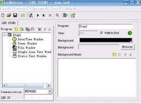
Figure 20-2
1.2. Connection diagram of Hardware, as shown in image 20-3 in below:
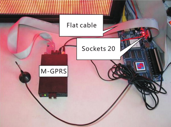
Figure 20-3
1.3 setup Software
Under multi-mode, there are two communication types for GPRS: IMEI configuration(recommended); GPRS virtual serial port configuration
steps for setting up LED editor:
Menu bar → Options → Software setup → Communication parameters, please select multi-mode then input password (default: 888), as shown in image 20-4 in below:
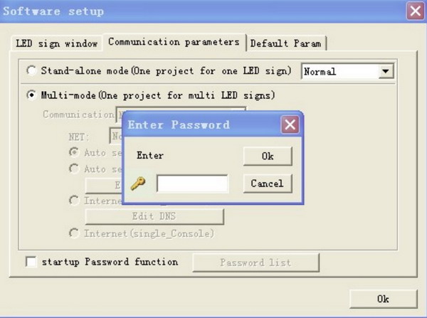
Figure 20-4
Then select IMEI configuration under GPRS mode, as shown in image 20-5 in below:
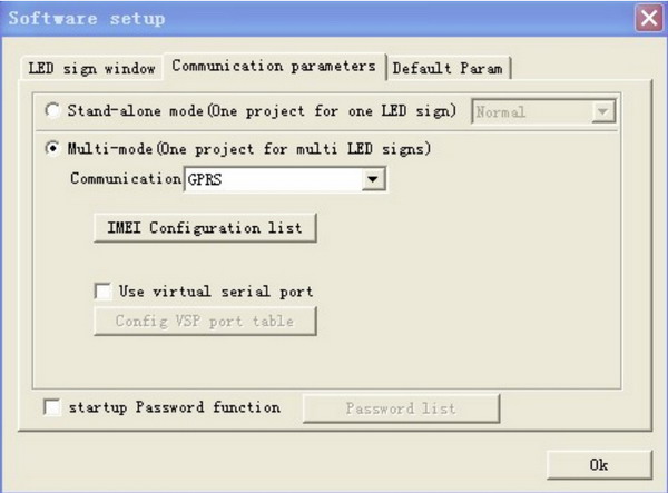
Figure 20-5
Click on “IMEI configuration list” then a dialogue box will appear, as shown in image 20-6 in below:
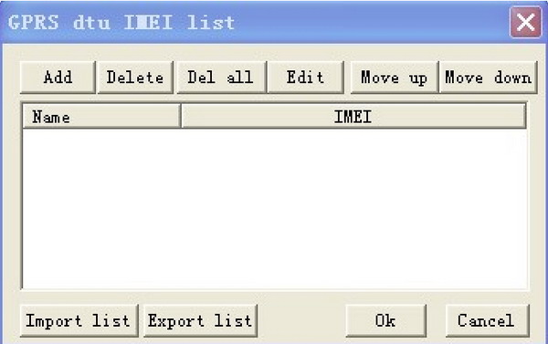
Figure 20-6
Click on “Add” button and add new terminal users, as shown in image 20-7 in below:
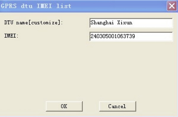
Figure 20-7
NOTE: press F5 on this interface then detailed information about GPRS terminal will appear, moreover, there is another GPRS mode: H7210 in dropdown list of DTU type for users, as shown in image 20-8 and 20-9 in below:
Interface of M-GPRS (do not change other contents)
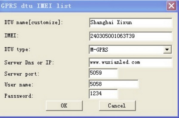
Figure 20-8
Interface of H7210
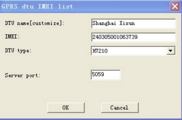
Figure 20-9
Click on “OK” button after configuring. Then click “Send” button, as shown in image 20-10 in below:
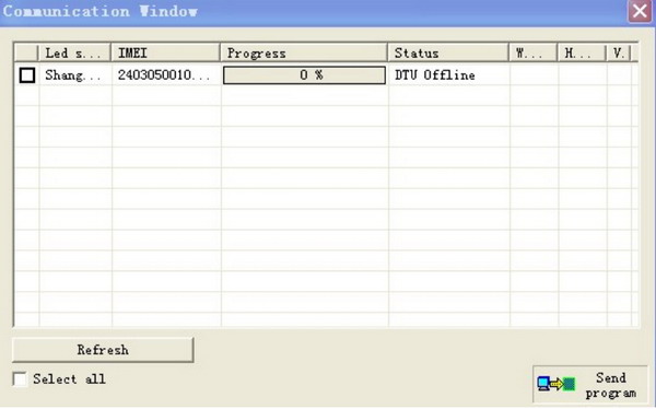
Figure 20-10
NOTE: Methods of changing M-GPRS DTU configuration
Configuration preparation and connection:
>> Insert web-enabled GPRS data card into SIM connector then connect M-GPRS Connect GPRS with PC by the serial port line
>> Connect M-GPRS antenna.
Login configuration interface:
Step 1: Running M-GPRS-DTU-CF.exe software, click on “Options” button then select the serial port number that PC connects with M-GPRS in the box of “COM Option”, click OK. Click on “Start Confg” button. (Turn on M-GPRS power within 15 seconds after clicking on “ start configuration”.)As shown in image 20-11 in below:
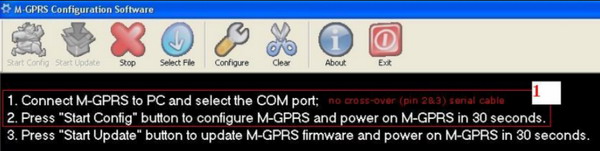
Figure 20-11
Step 2: Turn on M-GPRS power (power port is inner positive and exterior negative).
Step 3: When version information appears in configuration box, please press “enter” into configuration interface. In foreign country, please change APN parameters, as shown in image 20-12 in below:
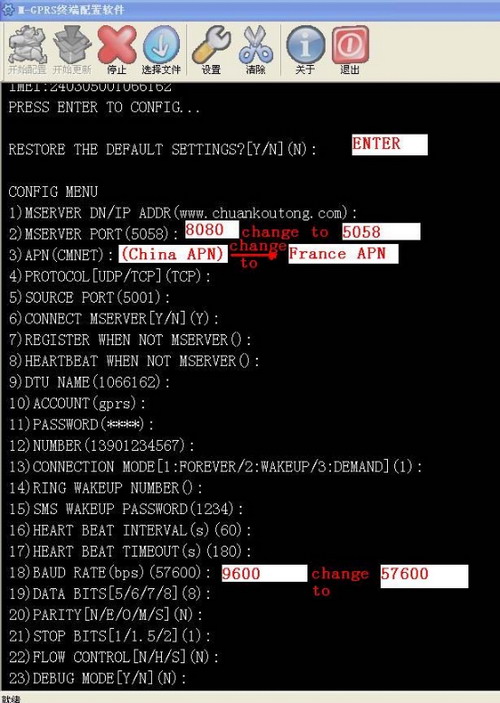
Figure 20-12
1.4 Configuring baud rate of serial port for control card
Under stand-alone mode, running LED Editor then selecting Network or COM communication type, Menu bar → Options → Hardware Setup, as shown in image 20-13 in below:
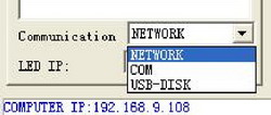
Figure 20-13
Baud rates of COM-R232 and M-GPRS DTU must keep consistent with each other. As shown in image 20-14 in below:
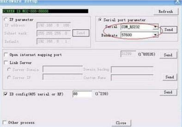
Figure 20-14
Related technical articles:
XIXUN 3G wireless controller Server solution - See more at: http://www.verypixel.com/blog/3G_wireless_controller_Server_solution.html
Verypixel 3G CONTROL SOLUTION - See more at: http://www.verypixel.com/service/LED_Billboard_3G_Control_Solution.html
Page address: http://www.verypixel.com/blog/Wireless_GPRS_Solution_for_LED_Display_Screen.html