Tag: LED Display Surrounding System Introduction, LED display accessories, Multifunction Card, Video Processor, Optical Converter, LED Display Switch Box, LED after-sales service

1. Multifunction Card Instruction


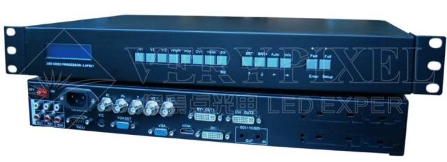
2. Video Processor Manual

1. Rear view

1.1 Port description
1.1.1 Video input (INPUT column)
LedSync820C supports 8-channel signal input, including:
|
Port name
|
Description
|
|
V1~V4
|
4-channel PAL/NTSC system composite video input
|
|
Y/C (S_Video)
|
1-channel PAL/NTSC system S_Video input
|
|
VGA
|
1-channel computer analog signal input
|
|
DVI
|
1-channel computer digital signal input
|
|
YPbPr
|
1-channel high-definition component signal input
|
1.1.2 Audio input
Corresponding to 8-channel video input signal, LedSync820C supports 8-channel stereo audio signal input.
1.1.3 Video signal output
|
Port name
|
Description
|
|
VGA OUT
|
1-channel analog RGBHV signal output, it can be connected to a local display device and used as monitor (it is strongly recommended to use this port when operating and setting LedSync820C).
|
|
DVI OUT
|
1-channel digital DVI signal output, it is to be connected with external LED transmission card or LED transmission box
|
1.1.4 Audio signal output
It corresponds to the selected video input signal, and output this channel audio input signals
1.1.5 Signals of other ports
|
Port name
|
Description
|
|
RS232 IN
|
Serial communication port, LedSync820C’s Timing Control Software running on Upper Controller can operate and control LedSync820C via this communication port.
|
2. Button operations:
LedSync820C have 14 buttons on frontal panel, after start-up all these buttons are in operation mode. Their functions are described as below:
2.1 Select input video source
|
Button names
|
Description
|
|
V1 to V4
|
Switch to V1~V4, composite video input
|
|
Y/C (S_Video)
|
Switch to S-Video input
|
|
VGA
|
Switch to computer analog signal input
Note: to get clarity computer image, you can click the “VGA” button 6 times continuously, and then you can click “VGA” button again and again to change the computer image sampling phase, when the computer image be displayed most clearly, the adjustment is ok.
|
|
DVI
|
Switch to computer digital signal input
|
|
YPbPr
|
Switch to high-definition component video signal input
Note: to get clarity HDTV image, you can click the “YPbPr” button 6 times continuously, and then you can click “YPbPr” button again and again to change the HDTV image sampling phase, when the HDTV image be displayed most clearly, the adjustment is ok.
|
Switch audio input while operating above buttons, select the audio signal input from corresponding video input to output it through Audio OUT.
Notes: when user has selected input signal, if there are signal input in corresponding signal input ports and are in LedSync820C formats, the indicator above corresponding button will be illumed. However, when there are no signal input in corresponding input ports, the indicator above corresponding button will blink, and dark screen will be displayed on the screen.
2.2 Select output brightness
|
Button names
|
Description
|
|
BRT-
|
Decrease output image brightness of LedSync820C
|
|
BRT+
|
Increase output image brightness of LedSync820C
|
LedSync820C supports 8 levels Brightness, "1" represents the lowest brightness, 8 represents the highest brightness. When brightness is adjusted to be "1", "3", "5" or "7", their LED indicators will blink; When brightness is adjusted to be "1", "3", "5" or "7", their LED indicators will keep illumed.
2.3 Select image status
|
Button names
|
Description
|
|
DEF
|
Select user-defined image parameters, including GAMMA value, Video Chrom and Hue. User can define custom parameters using PC software.
|
|
STD
|
Select a standard image status to output image. This standard image has been preset at factory, including GAMMA =1, Video Chrom and Video Hue = standard values. User can’t modify these standard values.
|
2.4 Select FULL/PART display (FULL, PART)
|
Button names
|
Description
|
|
FULL
|
FULL means that LED will display a full picture.
|
|
PART
|
PART means that LED only display a part of a picture.
|
3. RS485-optical Converter Specification

1. Product model: LQIC485OPT.05.0
2. Main technical data:
Working voltage: DC5V voltage range : DC 4.8V~DC5.3V
Working current: ≤200 mA
Optical model: single mode 1310nm optical
Transmission distance: ≤30km
Communication carrier: single mode Optical
Operating environment: temperature -10~+50℃
Relative humidity: ≤90%(40±°C)
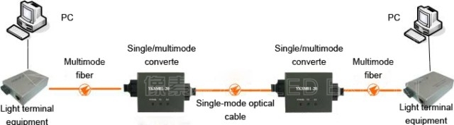
3. Input and Output interface and installation method:
This mode has a set of optical interface a 485 interface and a power supply interface.
Through the optical fiber can realize 485 equipment of high-speed distance peer-to-peer communication .
3.1 Polarity 485 bus interface: two lines : "A" connect with 485 Bus high-level . "B" connect with 485 low-level .
3.2 485 cable adopt RVS1.0mm2 ordinary Unshielded Twisted Pair cable ,Transmission distance can reach 1.2km , reduce cable usage number greatly , reduce project cost greatly .Besides , Unshielded Twisted Pair cable more thick, the transmission farther , Communication effect better . if adopt Shielded Twisted Pair cable , Communication effect better .485 cable communication speed rate : 0 to 1Mbps any speed rate self-adaption
3.3 DC5V Power supply connection :"DC5V+" connect with DC5V anode , "GND" connect with DC5V cathode . if not work , please check the connection is right or not .
3.4 Polarity fiber interface :double SC interface , "TX"connect with other converter "RX", "RX" Connect with other converter"TX", communications rate : 0 to 5Mbps any rate self-adaption.
3.5 communications rate : 0~5Mbps any rate self-adaption.
3.6 Between Optical Tail fiber (jumper wire) and engineering laying cable adopt welding technique .
4. Function:
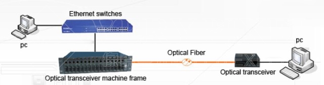
4.1 This product is used to extend the communicating distance of the 485 bus network, with the optical fiber for signal transmission medium, this product is able to be with long distance transmission, wide frequency band transmission, good insulation performance, strong ability of anti-radiation and anti-interference, light weight and corrosion resistance, etc. Especially suitable for nuclear radiation areas, Extra-High-Voltage power system, the areas with intense electromagnetic interference, mined areas, highly corrosive environment, flammable and explosive areas and so on.
4.2 Using the RS485 Optical Converter to connect the 485 bus cable with optical fiber, once it is in need of the long distance and anti-interference transmission, the RS485 signal can convert to optical fiber signal; Once it needs to connect to the 485 bus cable communicating device, the optical fiber signal can convert to RS485 signal.
4.3 The RS485 optical converter is with two way communication, nanosecond conversion, fast and transparent, plug into and play.
5. Notes
5.1 Fiber optic converters must be used in pairs, don't connect the power polarity reversely.
5.2 Before connecting to the optic fiber, the TX and RX port should be protected with plastic cover to avoid the dust and impurities.
5.3 The bending radius of the fiber shall not be less than 0.5m
4. LED Display Switch Box Direction
1. Function introduction
Distribution box is mainly used for power distribution to each load, and it can be power protection while there is the short circuit, overload and leakage. It mainly supply the power for the LED display, it can support AC380 voltage input, Air-switch protection, support 220V output. It is with special mechanism design, so that it can avoid the leakage. Besides, it is with a power indicator to indicate, safe for usage.
2.The circuit diagram of common power distribution box

3. Introduction of components of power distribution box
3.1 3P Air Switch: this switch is very important for the low-voltage distribution network and electric drive system. It integrates the controlling and various protection functions. Except switch on and off, it can also protect from the short circuit, serious overload, and low voltage. Besides, it can used to switch on the electric motor occasionally.
3.2 5V Power Supply: provide the 5V power for the controlling system and the function card.
3.3 Lightning Arrestor: It can release the thunder electricity and release the electricity to not allow it overload, protect the electrical equipment to avoid the transient voltage damage, and cut down the continues current to avoid the device short circuit. Lightning arrestor is usually connected between the live wire and the ground, and in parallel with the protected equipments.
3.4 Miniature Circuit Breaker: Circuit Breaker can be divided into high-voltage circuit breakers and low-voltage breakers according to their usage. Usually, we called the voltage above 3kV the high voltage. Low-voltage circuit breaker is called Automatic Switch, that is "Air Switch". It can not only switch on and off manually, and can also loss the voltage, be under voltage, overload and short circuit protection automatically. It can distribute the power, switch on the electric motor occasionally, protect the wires and circuit and electric motor, when there is serious overload or short circuit to them, it can cut down the current automatically. It is like the fuse switch and over and less thermal relay.
3.5 Contactor: It means the device which can take the advantage of industrial electricity coil generates the magnetic field, make the contactor closed, to control the overload. The contactor is composed of electromagnetic system, the contact system and the phosphate arc device. The principle is that, when the electromagnetic coil get the electricity, and generates the magnetic field, the electromagnetic response to the static core strength to attract the armature, and promote the contact action: normally closed contact is open; normally open contact is closed, the two is linked When there is no electricity in the coil, the electromagnetic suction disappeared, the armature is released after the spring released, the contact recovery: normally closed contact is closed; normally open contact is disconnected.
3.6 Terminal blocks: It is used to connect to the live wire.
3.7 Multi-functional card: Integrated functions of humidity collection, power switch and sound transmission.
3.8 Button switch.
3.9 Indication light.
4. Remarks and Notes while the operation of power distribution box
4.1 Inside the distribution box, all of the electrical components and wiring should be with good contact, reliable connection; Make sure there is no serious fever, burning phenomenon. The door of switch board should be with good condition; And there should be special man to keep the door and lock.
4.2 The distribution box should be cleaned and maintained regularly, to keep the equipment in good working condition.
5. The connection diagram between the power distribution box and LED display.

5.1 wire three phase 5 wires (3 L,1N and 1G) to the AC 380V input terminal block,while wire 2 phase 3 wires(1L,1N,1G)between the output AC 220V terminal block to LED display.
5.2 Connect the multi-function card to sending card in computer/IPC and receive card in first cabinet of LED display with internet cable (RJ45).
5.3 Switch on the 3P air switch to make the switch box function, then power indication/alarm lamp will be green.
5.4 Turn on your computer which has already programmed with our control system software,You can find the indication lamp on Multi-functional card flicker green.
5.5 Now you have three ways to turn on and turn off the screen Push/pull the 3P air switch (Turn on or Turn off both switch box and LED display) Push the power button (Turn on or Turn off the LED display) Use software in computer/IPC (Turn on or Turn off the LED display).
6. The main features of power distribution box
a. To provide the AC220 power supply.
b. While the urgent occasion, you can cut down the power supply according to the PC, manual operation and sensor the three methods.
c. Equipped with 4 wheels in the bottom for moving freely.
d. Stable and reliable performance.
e. AC380V input, and with thunder protection.
Page address: http://www.verypixel.com/service/LED_Surrounding_System.html